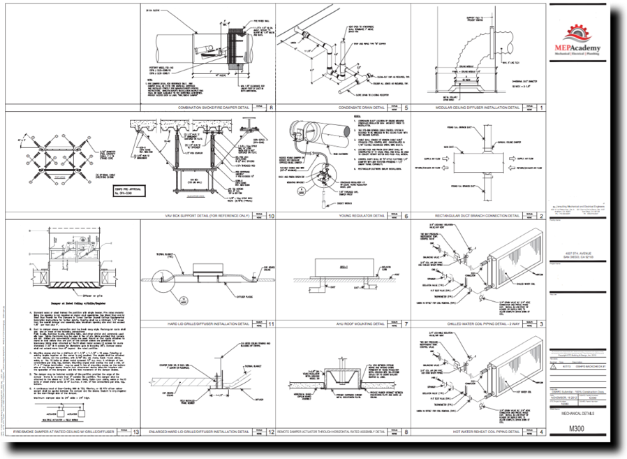
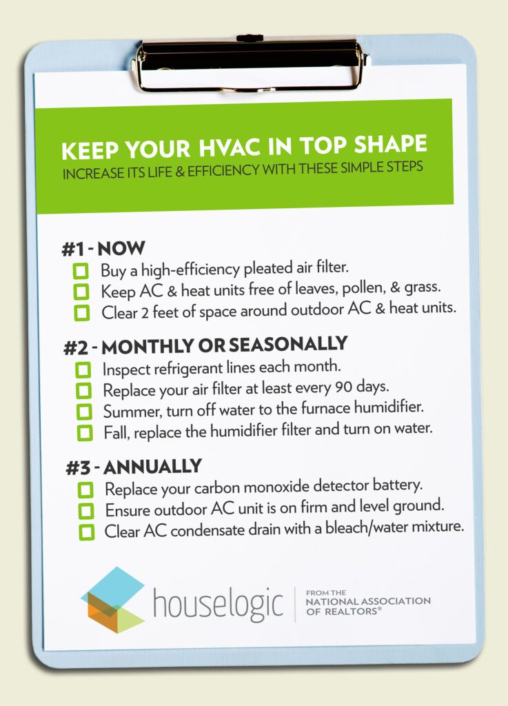
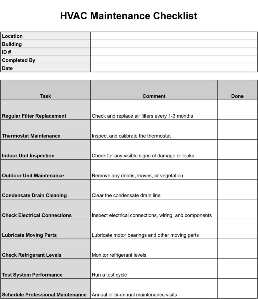
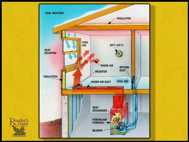
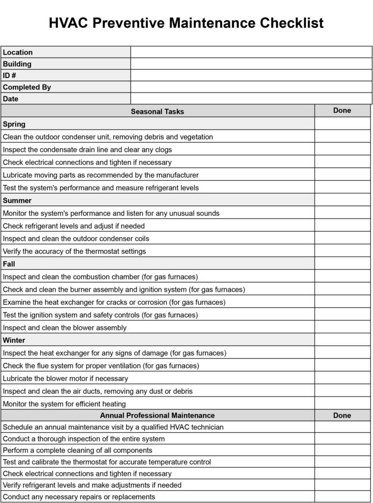
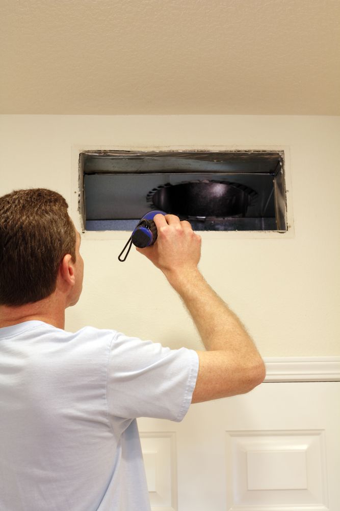
In this article, we will explore the world of HVAC drawings and discover what they truly entail. These drawings serve as a crucial blueprint for professionals in the heating, ventilation, and air conditioning industry, providing a comprehensive visual representation of the system’s design and layout. From ductwork and equipment placement to electrical connections and control systems, HVAC drawings reveal the intricate details that ensure efficient and effective heating and cooling in our homes and buildings. So, let’s delve into the fascinating realm of HVAC drawings and uncover the secrets they hold!

Types of HVAC Drawings
Floor Plans
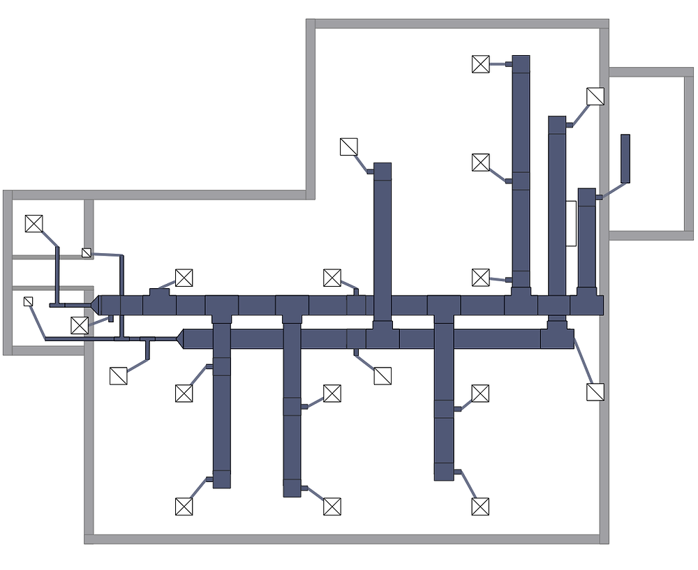
Floor plans are an essential part of HVAC drawings as they provide a detailed representation of the building’s layout. These drawings show the location of walls, windows, doors, and other architectural elements that need to be considered when designing the HVAC system. By using floor plans, HVAC engineers can accurately determine the most suitable locations for equipment, vents, and ductwork. With this information, they can ensure that the HVAC system is appropriately placed to provide optimal heating and cooling throughout the building.
Elevation Drawings
Elevation drawings provide a vertical representation of the HVAC system. These drawings showcase the height and arrangement of equipment, ducts, and vents. By utilizing elevation drawings, HVAC engineers can assess the overall design of the system, including any potential conflicts or space limitations. This allows them to make informed decisions about the placement and size of equipment to ensure efficient operation and proper air distribution.
Section Drawings
Section drawings provide a cross-sectional view of the HVAC system, enabling engineers to visualize the internal components and how they interact with the building structure. These drawings are particularly helpful in identifying potential issues with space constraints or obstructions that may affect the installation or maintenance of the HVAC system. By utilizing section drawings, HVAC engineers can accurately assess the system’s design and make any necessary adjustments before the installation process begins.
Schematic Diagrams
Schematic diagrams are essential for understanding the electrical and control aspects of the HVAC system. These diagrams illustrate the wiring connections, control components, and safety systems that ensure the system operates effectively and safely. By referring to the schematic diagrams, HVAC technicians can troubleshoot and maintain the system accurately. Schematic diagrams also aid in the communication between engineers, technicians, and equipment manufacturers, ensuring everyone is on the same page when it comes to the system’s functionality.
Symbols and Notations
Standard Symbols
Standard symbols are used throughout HVAC drawings to represent various components and equipment. These symbols provide a universal language that allows engineers, technicians, and contractors to understand and interpret the drawings accurately. By using standardized symbols, HVAC professionals can communicate effectively and ensure consistency in plans and designs. Some common standard symbols used in HVAC drawings include those for equipment such as furnaces, air conditioners, and fans, as well as symbols for control valves, dampers, and sensors.
Identifying Equipment
In HVAC drawings, it is crucial to accurately identify the different equipment used in the system. This includes labeling specific components and indicating their purpose and function. By clearly identifying equipment, HVAC professionals can avoid confusion and ensure that the system is installed and operated correctly.
Labeling
Labeling is an essential aspect of HVAC drawings as it provides clear and concise information about various elements of the system. This can include labeling ducts, equipment, control panels, and connections. By using consistent labeling throughout the drawings, HVAC professionals can easily locate and identify different components, which is crucial for maintenance, repairs, and troubleshooting.
Color Coding
Color coding is often used in HVAC drawings to enhance clarity and organization. Different colors can be assigned to various elements, such as ducts, pipes, electrical wiring, and control systems. This visual differentiation makes it easier for HVAC professionals to understand the layout and quickly identify specific components. Color coding also aids in the communication of complex systems, making it easier to follow and interpret the drawings.

Ductwork and Ventilation
Duct Layout
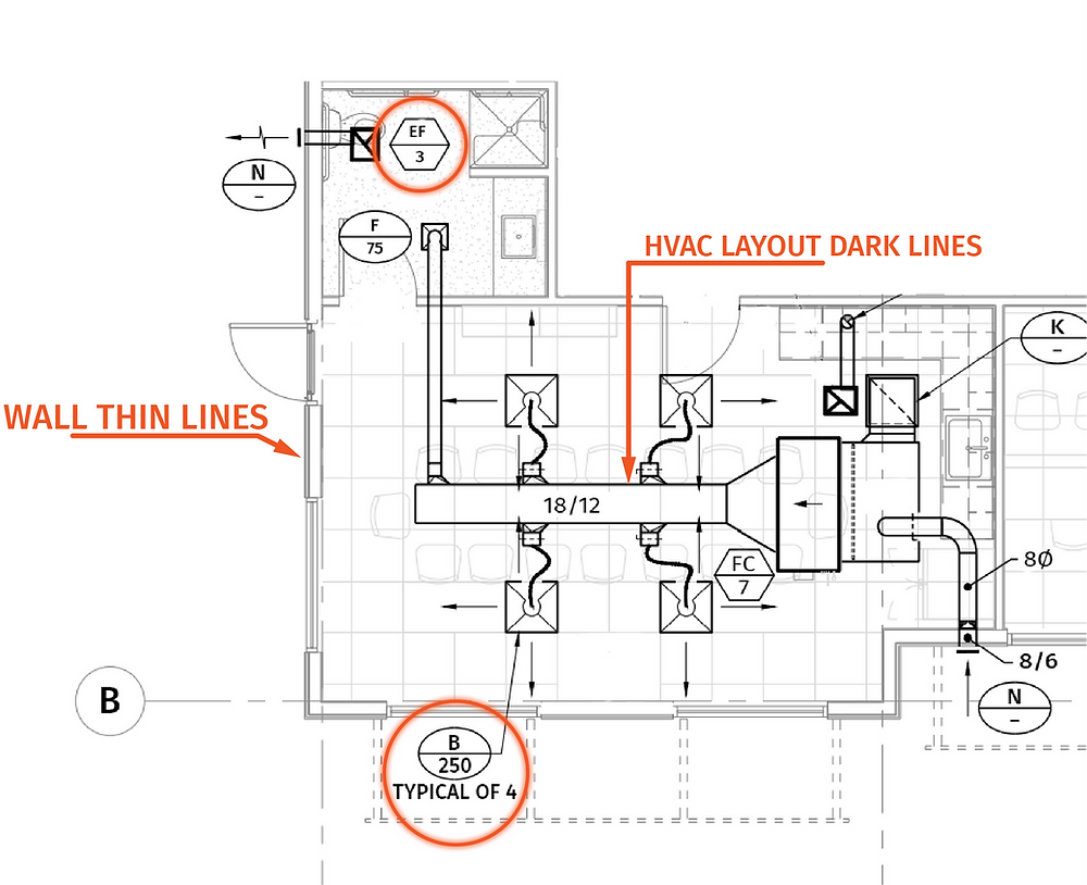
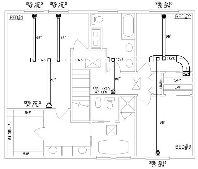
Duct layout drawings show the routing of the ductwork throughout the building. These drawings indicate the size and arrangement of ducts that are responsible for delivering conditioned air to different areas. This includes the placement of supply vents and return air registers. By carefully planning the duct layout, HVAC engineers can ensure the efficient distribution of air and maintain a comfortable indoor environment.
Size and Shape
The size and shape of ductwork are crucial factors in determining the airflow capacity and overall performance of the HVAC system. HVAC drawings provide information on the dimensions and design of the ducts, including the cross-sectional area and the material used. By accurately sizing and shaping the ducts, HVAC professionals can optimize airflow and minimize energy loss.
Airflow Direction
HVAC drawings indicate the airflow direction within the ductwork system. These drawings showcase the movement of air from the supply vents to the return air registers. By ensuring the correct airflow direction, HVAC professionals can maintain balanced air distribution and improve indoor air quality.
Location of Fans and Filters
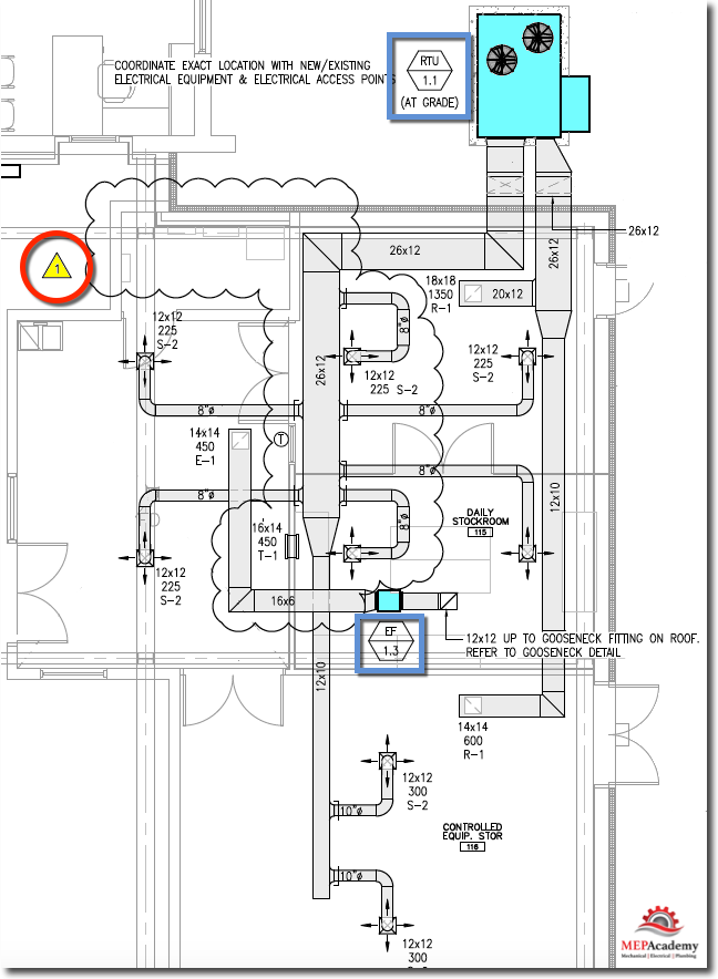
Fans and filters play a vital role in the HVAC system’s operation, and their correct placement is crucial for optimal performance. HVAC drawings provide information on the location of fans, such as air handling units or exhaust fans, and filters within the system. This enables HVAC professionals to ensure that these components are appropriately positioned to facilitate the movement and filtration of air effectively.
Piping and Plumbing
Piping Layout
Piping layout drawings show the arrangement and routing of pipes within the HVAC system. These drawings indicate the location of hot and cold water pipes, refrigerant lines, and fuel lines, among others. By designing an efficient piping layout, HVAC professionals can ensure the proper flow of fluids and maintain the desired temperature levels.
Pipe Sizes and Materials
Selecting the appropriate pipe sizes and materials is essential to optimize the HVAC system’s performance and longevity. HVAC drawings provide information on the diameter, thickness, and material of pipes used in the system. By using the correct sizing and materials, HVAC professionals can minimize pressure drops, prevent leaks, and ensure the system operates efficiently.
Connection Points
Connection points refer to the specific locations where pipes are joined together or connected to equipment. HVAC drawings highlight these connection points, such as valves, fittings, and flanges, to ensure proper installation and maintenance. By following the drawings, HVAC professionals can accurately connect pipes, preventing potential leaks and ensuring seamless operation.
Plumbing Fixtures
Plumbing fixtures, such as sinks, toilets, and showers, are integral parts of the HVAC system, particularly in buildings with water-based heating or cooling systems. HVAC drawings include information on the location and arrangement of these fixtures. By incorporating plumbing fixtures into the drawings, HVAC professionals can coordinate with plumbing contractors and ensure that the system meets all the necessary requirements.

Electrical Wiring
Power Supply Connections
Power supply connections refer to how electrical power is supplied to the HVAC system. HVAC drawings provide detailed information on the electrical wiring, including the location of main power panels, circuit breakers, and disconnect switches. By accurately depicting the power supply connections, HVAC professionals can ensure safe and reliable operation of the system.
Control Wiring
Control wiring is responsible for connecting the HVAC system’s control components, such as thermostats, sensors, and switches, to ensure proper operation. HVAC drawings indicate the routing and placement of control wiring, allowing HVAC professionals to identify the connections and troubleshoot any issues that may arise.
Equipment Wiring
Equipment wiring refers to the electrical connections within HVAC equipment, such as furnaces, air conditioners, and heat pumps. HVAC drawings provide information on the wiring connections and ensure that the equipment is correctly integrated into the overall system. This helps HVAC professionals in installation, maintenance, and repairs, ensuring the equipment functions optimally.
Safety Systems
Safety systems are vital in HVAC installations to protect the system and the occupants of the building. HVAC drawings include information on safety devices such as electrical disconnect switches, overload protections, and emergency shutdown switches. By incorporating safety systems into the drawings, HVAC professionals can ensure that the HVAC system meets all safety regulations and operates reliably.
Zoning and Controls
Thermostats and Sensors
Thermostats and sensors are essential components for controlling the temperature and comfort levels within different zones of a building. HVAC drawings indicate the locations of thermostats and sensors, ensuring proper positioning for accurate temperature monitoring and control. By following the drawings, HVAC professionals can create a zoned system that maximizes energy efficiency and occupant comfort.
Dampers
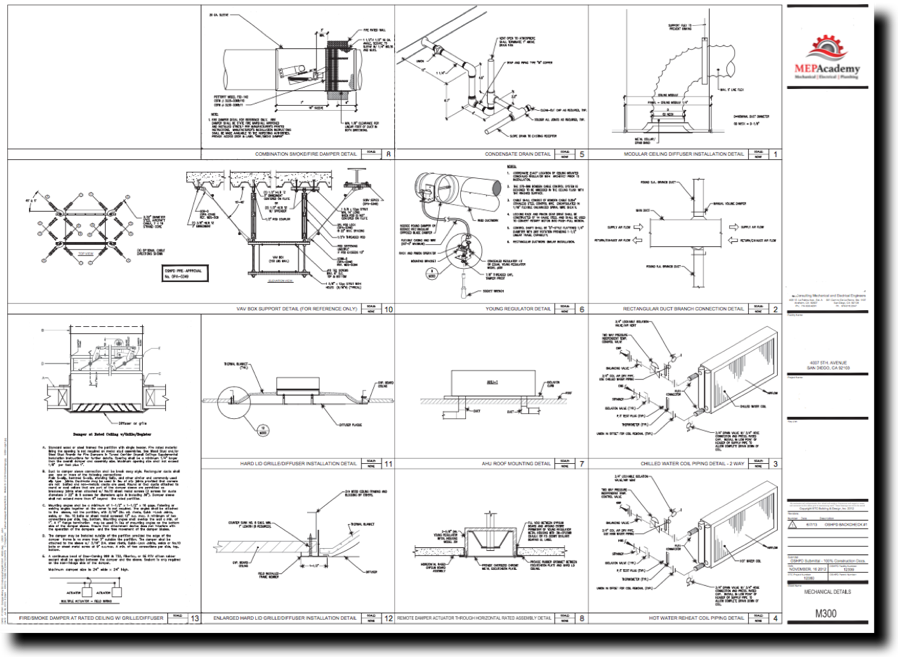
Dampers are used to regulate and control the airflow within HVAC systems. HVAC drawings provide information on the placement and operation of dampers, including motorized dampers and fire dampers. By incorporating dampers into the system design, HVAC professionals can balance airflow, prevent air leakage, and comply with fire safety regulations.
Zones and Temperature Control
Zoning refers to dividing a building into multiple areas or zones, each with individual temperature control. HVAC drawings indicate the zoning arrangement, allowing HVAC professionals to design and install the necessary equipment and controls for each zone. This ensures personalized comfort and energy efficiency throughout the building.
Integrated Building Automation Systems
Integrated building automation systems connect various HVAC components and controls to provide centralized management and monitoring. HVAC drawings show the integration and interconnection of different systems, such as HVAC, lighting, and security. By utilizing integrated building automation systems, HVAC professionals can optimize energy usage, improve system performance, and simplify facility management.

Equipment and Components
Furnaces and Boilers
Furnaces and boilers are responsible for providing the heating requirements of a building. HVAC drawings provide information on the placement and connectivity of furnaces and boilers, including combustion air supply, flue gas venting, and fuel connections. By accurately incorporating furnaces and boilers into the drawings, HVAC professionals can design and install efficient heating systems.
Air Conditioners and Heat Pumps
Air conditioners and heat pumps are used for cooling and, in the case of heat pumps, heating a building. HVAC drawings indicate the locations, sizes, and refrigerant connections of these cooling devices. By properly locating and sizing air conditioners and heat pumps, HVAC professionals can ensure effective cooling and heating throughout the building.
Air Handlers
Air handlers are essential components of HVAC systems responsible for circulating and conditioning air. HVAC drawings provide information on the location, sizing, and duct connections of air handlers. This ensures optimized airflow and proper distribution of conditioned air within the building.
Filters and Humidifiers
Filters and humidifiers play a crucial role in maintaining indoor air quality and comfort. HVAC drawings include the placement and dimensions of filters and humidifiers within the system. By incorporating filters and humidifiers into the drawings, HVAC professionals can ensure proper installation and maintenance, promoting clean and healthy indoor air.
Exhaust Systems
Kitchen Exhausts
Kitchen exhaust systems are designed to remove smoke, cooking odors, and grease particles from commercial kitchen areas. HVAC drawings indicate the exhaust hood location, duct routing, and fan installation. This ensures effective removal of kitchen pollutants and maintains a safe and clean kitchen environment.
Bathroom Exhausts
Bathroom exhaust systems are necessary to remove excessive moisture and odors from bathrooms. HVAC drawings show the placement of bathroom exhaust fans, duct routing, and termination points. By incorporating bathroom exhausts into the drawings, HVAC professionals can ensure efficient ventilation and prevent the growth of mold and mildew.
Fume Hoods
Fume hoods are crucial in laboratories and manufacturing facilities to protect workers from hazardous fumes and airborne contaminants. HVAC drawings indicate the placement, duct connections, and exhaust requirements for fume hoods. By following the drawings, HVAC professionals can ensure the proper function and safety of fume hoods.
Exhaust Fans
Exhaust fans are used to remove stale air and maintain proper airflow in various areas of a building. HVAC drawings provide information on the placement, size, and duct connections of exhaust fans. This ensures effective ventilation and prevents the buildup of airborne pollutants and odors.

Fire Protection
Fire Dampers
Fire dampers are critical components in HVAC systems to prevent the spread of fire and smoke through ductwork. HVAC drawings indicate the location and installation details of fire dampers, including testing and maintenance access points. By incorporating fire dampers into the drawings, HVAC professionals can ensure compliance with fire safety regulations and enhance the overall fire protection system.
Fire Sprinkler Systems
Fire sprinkler systems are designed to automatically suppress fires and prevent them from spreading. HVAC drawings show the coordination between HVAC components and fire sprinkler systems, such as proper spacing and avoidance of obstructions. By incorporating fire sprinkler systems into the drawings, HVAC professionals can ensure effective fire suppression and enhance the safety of the building.
Fire Alarm Systems
Fire alarm systems are critical in providing early warning of fire incidents and initiating appropriate emergency responses. HVAC drawings indicate the integration of HVAC components with fire alarm systems, such as smoke detectors, audible alarms, and emergency shutdowns. By following the drawings, HVAC professionals can ensure reliable fire detection and alarm functionality.
Emergency Exits
Emergency exits are vital for a safe evacuation during a fire or other emergencies. HVAC drawings indicate the locations and design considerations for emergency exits, such as the placement of exit signs and coordination with HVAC ductwork. By incorporating emergency exits into the drawings, HVAC professionals can ensure compliance with building codes and enhance occupant safety.
Construction Details
Insulation
Insulation plays a crucial role in preventing heat loss or gain and reducing energy consumption. HVAC drawings provide information on the insulation materials and locations, such as insulation around ductwork or pipes. By accurately depicting insulation details, HVAC professionals can ensure the proper installation and effectiveness of insulation within the system.
Vibration Isolation
Vibration isolation is essential to minimize the transmission of noise and vibrations from HVAC equipment to the building structure. HVAC drawings indicate the use of vibration isolation materials, such as rubber pads or isolators, and their placement. By incorporating vibration isolation into the drawings, HVAC professionals can prevent structural damage and ensure occupant comfort.
Access Panels
Access panels are necessary for easy maintenance and servicing of HVAC equipment and components. HVAC drawings indicate the location and size of access panels, ensuring convenient access for technicians. By incorporating access panels into the drawings, HVAC professionals can facilitate efficient maintenance and reduce downtime for the HVAC system.
Supports and Hangers
Supports and hangers are essential for securely installing HVAC equipment, ductwork, and piping. HVAC drawings provide information on the placement, type, and spacing of supports and hangers. This ensures the proper support and stability of the system, preventing sagging or displacement over time.
In conclusion, HVAC drawings are invaluable tools for the design, installation, and maintenance of heating, ventilation, and air conditioning systems. By encompassing various types of drawings, symbols, and notations, these drawings provide a comprehensive guide for HVAC professionals to create efficient, safe, and comfortable indoor environments. Whether it’s the layout of ductwork, electrical wiring connections, or the integration of fire protection systems, HVAC drawings are essential in ensuring the successful implementation of HVAC systems in buildings of all types and sizes.

